Uncovering the Instrument Voltage Regulator and the LM7805

This area is open to"How-To" section only for tutorials on fixes, etc. (no profanities/etc.). NO FOR SALE POSTINGS

Moderator: redstangbob

Post Reply
User avatar
ABQTBird
Posts: 1183
Joined: Mon Feb 06, 2012 1:13 am
Location: Land of Enchantment
Contact:

Uncovering the Instrument Voltage Regulator and the LM7805

Post by ABQTBird »

The instrument voltage regulator or IVR, sometimes called the constant voltage regulator or CVR (although that is a misnomer) controls the voltage going to the fuel and temperature gauges by stepping 12V down to 5V mechanically. Before proceeding, please watch this YouTube video that will only take two minutes of your time and I hope you will find quite interesting:
http://youtu.be/a1ou2WHdylY

The replacements are quite expensive. The contacts also wear over time producing inaccurate voltages which will affect the accuracy of the two instruments. Here is a method of replacing the primitive mechanical regulator with the LM7805 voltage regulator that you can get for $2 at Radio Shack or on Ebay.

First, open the case. I used a small pair of channel-lock type pliers to work my way around the lip of the case.
Image

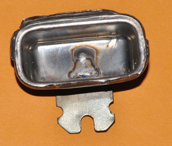
Here is one that I burned out a long time ago. The coil has overheated around the bi-metalic arm and is now useless.
Image

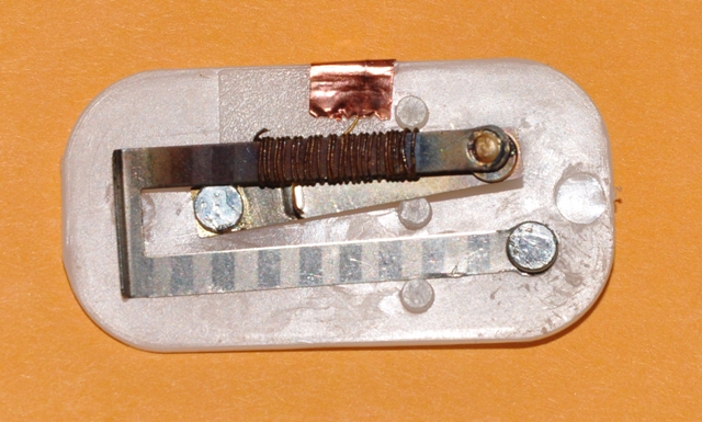
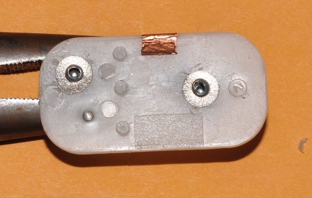
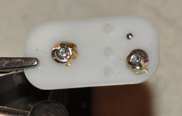
Here is a view of the contacts and adjustment screw. They are set at the factory to emulate somewhere around 5V maximum with the screw. Notice the piece of copper foil is used to ground the 12V coil to the case and to the body of the car.
Image

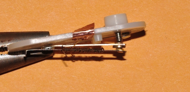
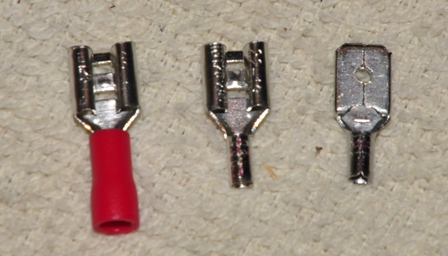
I pulled the connectors out of the existing contacts to the metal arms and re-riveted them using a pop rivet gun and the smallest rivets I had.
Image

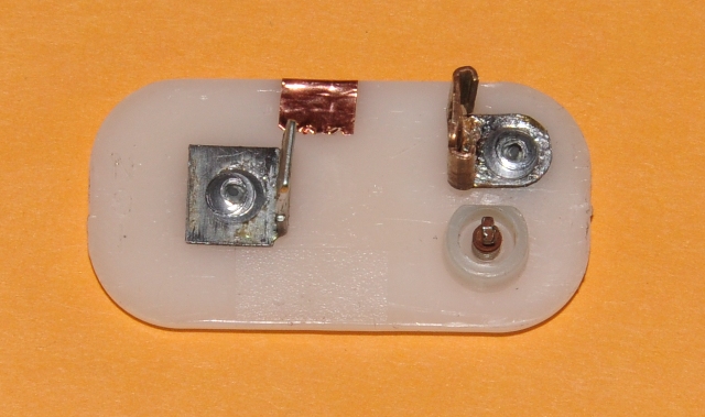
Here is a view of the rivets on the inside of the case. I have used some #4 washers to reinforce the rivets.
Image

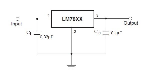
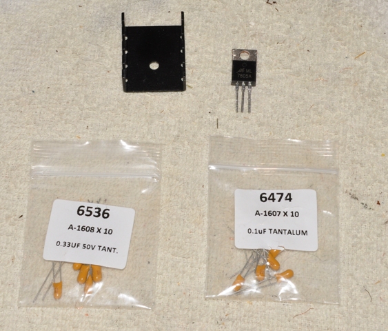
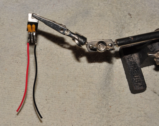
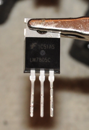
The next step is to prepare the 7805 regulator. A typical circuit that you will find in the 7805 datasheet and on the Internet calls for two capacitors, one on the input side and one on the output to reduce minor oscillations in the voltage. For this application, I am going to skip the capacitors, as they are not needed. After years of pounding oscillation from the IVR, your instruments won't mind a few millivolts of oscillation now and then. The contact on the left is voltage in, the middle contact and mounting tab is ground, and the contact on the right is 5V out.
Image

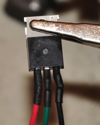
Cut off the leads at the point where they widen and then solder three color coded wires to the leads and cover them with shrink tubing.
Image

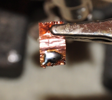
Add a dab of solder to the copper foil and to the rivets on the inward facing side of the plastic piece.
Image
Image

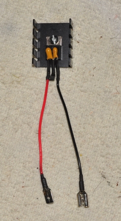
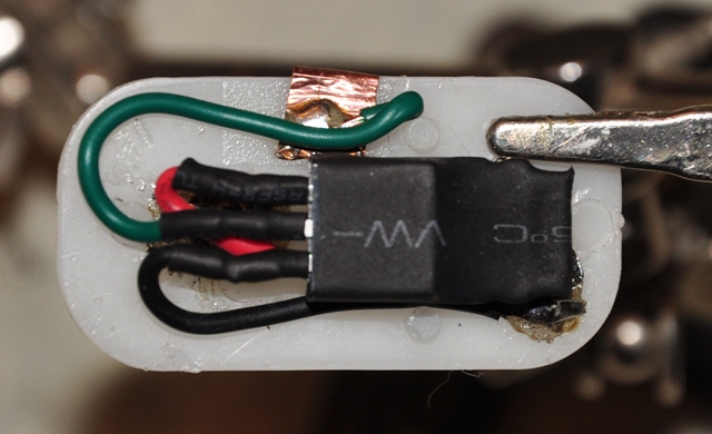
Now solder the 12V red wire to the terminal lableled IGN and the black wire to the output terminal. The green wire gets soldered to the piece of copper ground foil. I have covered the entire regulator with heat shrink tubing to prevent the attachment tab (which is ground) from touching contacts inside the case.
Image

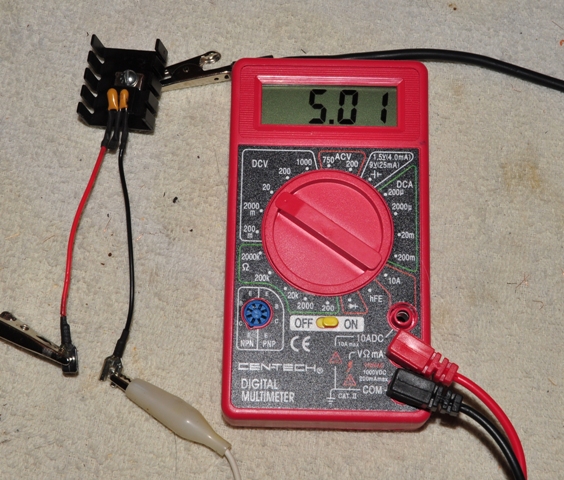
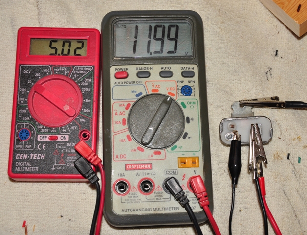
Before you seal it up in the case, bench test it with a power supply by connecting the copper foil to ground. Attach 12V to the IGN side of the regulator and the positive lead of your meter to the the output of the regulator and the negative side to ground of the power supply. If you get 5V, then you are ready to seal it up. Be sure the copper foil makes contact with the case at the outer edge. Now there is a steady voltage of 5V that will not change regardless of the the voltage applied to the input (5V to 18V).
Image

If you browsed for these on Ebay, you may have come across these solid state regulators for about $25. For $2, some solder and some patience, you can have the same regulator.

If you really want to stick to originality, you can reattach the radio noise suppression choke to the regulator. It will do nothing in this pure DC circuit.
Last edited by ABQTBird on Thu Aug 29, 2013 11:41 pm, edited 2 times in total.
Tom in Albuquerque
61-63 Forum Moderator
1962 Corinthian White Hardtop, Medium Chestnut Metallic #89 Leather, A/C, P/W
2003 Premium Torch Red/Performance White HT, Partial Accent Interior, 1 of 47.
Past T-Bird: 1960 Convertible, 1974-1978
User avatar
redstangbob
Posts: 3604
Joined: Fri May 02, 2008 4:06 pm
Location: 40 miles east of Wixom

Post by redstangbob »

Very good info Tom, thank you. I converted to the 7805 a few years ago, and never had an issue since. I did attach mine to a heat sink, as I believe the chip gets somewhat hot. GOOD STUFF :eek: Bob C
It's gonna be cool when it's done
And now it's really cool !!


59 convertible
58 convertible
65 hardtop
User avatar
ABQTBird
Posts: 1183
Joined: Mon Feb 06, 2012 1:13 am
Location: Land of Enchantment
Contact:

Post by ABQTBird »

I bought the heatsink but decided to do this for those who prefer to keep everything authentic. I might put one together with the capacitors and the heat sink just to see how it fits in the original location. Thanks!
Tom in Albuquerque
61-63 Forum Moderator
1962 Corinthian White Hardtop, Medium Chestnut Metallic #89 Leather, A/C, P/W
2003 Premium Torch Red/Performance White HT, Partial Accent Interior, 1 of 47.
Past T-Bird: 1960 Convertible, 1974-1978
User avatar
Tbird100636
Posts: 443
Joined: Thu Jun 11, 2009 1:25 am
Location: Braintree, Massachusetts

Post by Tbird100636 »

Hmmm... the IVR in our 64 just happens to be dieing. Lasted over 10 years surprisingly. I think I'll replace it with the solid state version.
1964 Thunderbird Hardtop- 390 FE 4V- Chantilly Beige- NEVER done, but beautiful as is.
1966 Thunderbird Convertible- 390 FE 4V- Red (Originally Wimbledon White)- Hood installed and repaint coming... well... not sure when...
User avatar
ABQTBird
Posts: 1183
Joined: Mon Feb 06, 2012 1:13 am
Location: Land of Enchantment
Contact:

Another method using capacitors and a heat sink

Post by ABQTBird »

If you want to skip the original housing and just want to do a quick build, this is what I did this time, including the capacitors, to make this circuit from the datasheet:
Image

To conserve space I bought tantalum 0.33 and 0.1 uF capacitors for a few dollars on Ebay. You can substitute small electrolytic or ceramic disk capacitors also. I think they can be up to 10uF. The heat sink is a TO-220 available at Radio Shack.
http://www.radioshack.com/product/index ... Id=2102856
Image

Closer view of the capacitors. They are marked 104 and 334 if you get them mixed up. The long lead is positive.
Image

With whatever method you can figure out, solder the caps to the regulator, negative side to the center ground. Then cut the leads to shorten it a bit.
Image

Solder the wires on and cut them to whatever length you like, then cover the three leads with heat shrink tubing.
Image

At the connector end I pulled the insulators off of the small red crimp connectors and soldered them on rather than crimp them. The male will go on the positive side. Don't forget to put some heat shrink tubing up the wire before soldering, as I did on one.
Image

Here is the completed assembly and test. I didn't try mounting it in the original location yet, but the mounting screw must be attached to a good ground. If the unit isn't well grounded, 12V will pass through the output. Alternatively, you could attach a wire to the center lead and put a connector on it and connect it to ground in the car.
Image

Image
Tom in Albuquerque
61-63 Forum Moderator
1962 Corinthian White Hardtop, Medium Chestnut Metallic #89 Leather, A/C, P/W
2003 Premium Torch Red/Performance White HT, Partial Accent Interior, 1 of 47.
Past T-Bird: 1960 Convertible, 1974-1978
hwoodlive
Posts: 2
Joined: Mon Mar 29, 2021 5:17 pm

Re: Uncovering the Instrument Voltage Regulator and the LM7805

Post by hwoodlive »

The LM7805 in the case, ready for assembly.
Hi Everyone, I also went the build-it-yourself electronic route after purchasing a brand-new IVR and finding it defective. The old one (itself some older replacement) in my '57 had shorted, sending 12V to the gauges. I bought an incredibly overpriced Made-In-China IVR from one of the well-known T-Bird parts vendors, and it didn't pass any voltage at all. It appeared to be a combination of poor rivets holding the connectors, and a really cheesy ground for the heating coil wire: there was no small metal plate to help ground that tiny wire to the case. It was just pinched between the case and the bakelite base. They might as well have attached a note reading "good luck!".
Contributors to this forum were very helpful in steering me to the DIY LM7805 solution, which has worked great for me so far. I used the case from the new Chi-com IVR, as its flimsier aluminum construction was easier to work with. LM7805's and the capacitors are easy to find online (I bought the capacitors but decided not to use them since minor voltage fluctuations weren't going to be an issue). Where I departed from the two general schools of thought on this forum were whether to use the original IVR case, or switch to a heatsink. I elected to combine those two methods, and used the IVR case AS the heatsink. That also eliminated the need for connecting the LM7805's center/ground terminal, as bolting the LM7805 to the IVR case supplied that ground. I attached the LM7805 to the IVR case with a small screw (which, yes, sacrificed any completely authentic appearance, but my car ain't no concours machine), then soldered jumpers onto the IVR bakelite base's Ignition and Gauge terminals. I'd already gutted the cheap IVR's internals, including the calibrating set-screw.
Since things are fairly cozy inside that IVR case, I cut a strip of cardboard, applied electrical tape, and inserted it between the LM7508 and the bakelite to ensure nothing touched what it wasn't supposed to be touching. Is the IVR case as efficient a heatsink as a made-for-that-purpose unit? Probably not, but it seems like it should do way better than just putting the LM7805 inside the case without the grounding screw.
The finished product.
Current T-Bird: 1957, 312V8, 3-speed manual, no soft top
Past T-Bird: 1967 2-door hardtop
andy2175m4
Posts: 99
Joined: Wed Feb 14, 2007 11:22 am
Location: Los Angeles, CA

Re: Uncovering the Instrument Voltage Regulator and the LM7805

Post by andy2175m4 »

I bought this goodie from Marlin P. Jones Inc. and zip tied it to the wiring harness, got rid of old IVR regulator, it was just not putting out enough voltage to move the gauges to where they should be, now I just nudge up the regulator 'til the gauges read reality ...it's bulky and won't fit in the old case, so it's a stand-alone, not a direct replacement. For some reason my temp and oil gauges would not read until I bumped it up to about 6.7 volts, must the corroded wires, etc. A new gas gauge sender helped too.
Attachments
regulator.jpg
regulator.jpg (8.24 KiB) Viewed 5225 times
Post Reply