Making a bench testing power supply from a computer P/S
Posted: Tue Jul 23, 2013 12:49 am
It is often useful to have a safe power supply that you can use to test parts on your T-Bird such as window motors, starter relays, bulbs, switches, clocks, horns, radios, etc. Using a car battery is not recommended as the current potential is far too high and any device connected to it must be protected with a fuse. Battery chargers also make poor power supplies as they too do not offer overload protection either. A computer power supply is ideal for bench testing. It is extemely sensitive to short circuits and will shut down immediately when a fault is detected. A typical 400W power supply offers about 17A or more of current at 12V, enough to test just about any electrical part in the car.
Here is what you need for a basic setup:
*An ATX type power supply. These are the most common and have been used for at least the past 10 years. You can get them from Newegg.com for about $20:
http://www.newegg.com/Product/Product.a ... 6817170016 or, in my case, I have a computer shop near me that sells used power supplies for $10-$15.
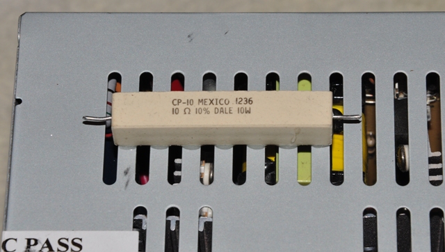
*A 10 ohm 10W ceramic resistor. These can be found in the drawers at Radio Shack for about $2.50 for two. RS also sells them on Ebay for $1.21: http://www.ebay.com/itm/360682691965?ss ... 1439.l2649
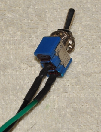
*A small single pole single throw (SPST) switch. This is another Radio Shack item that you can get for about $1.50.
*Solder and a soldering iron, a wire cutter and stripper, heat shrink tubing or electrical tape, and two part epoxy, JB Weld, or silicone adhesive.
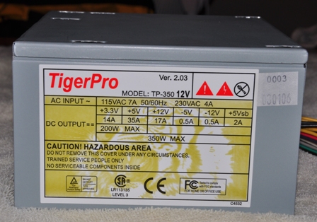
Here is the power supply I used. It is an old 350W model that can provide 17A at 12V. Another useful aspect is that you can also get 5V for testing instruments or driving electronic circuits if you are interested in that sort of thing, and 3.3V which you can use to test LED's without using a resistor:
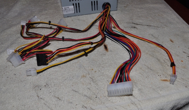
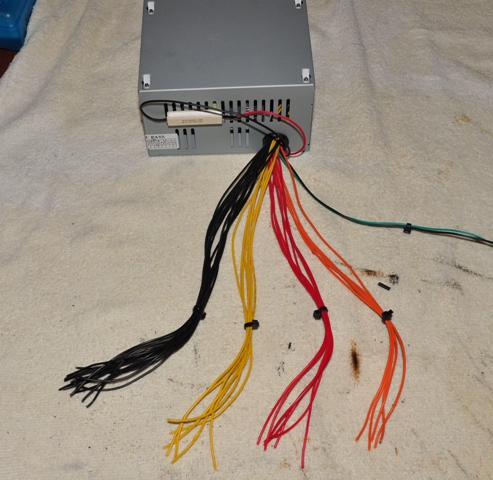
Layout the power supply and you will see a lot of wires. The yellow wires are 12V, the red are 5V, the orange are 3.3V and all the blacks are ground. There are some other colors that are not needed.
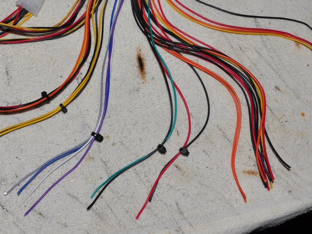
Cut all of the wires off of the large 20 pin connector. The purple, gray, white, and blue wires are not needed. Pair one of the black wires with the green wire, and another black wire with a red wire.
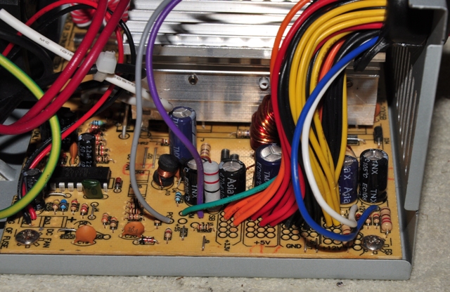
This is optional, but if you want you can open the power supply and cut off the purple, gray, white, and blue wires at the circuit board. This is safe. just avoid the very large capacitors on the other side of the power supply. They will not have a charge in them anyway if the power supply has not be on in the past day or so.
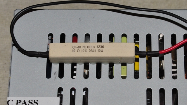
Glue the 10 ohm resistor to the cooling slots on the side and allow it to harden, then cut the leads off to about 1/4".
Solder a black and a red wire to either side of the resistor and cover the connections with shrink tubing or electrical tape.
Solder the green wire and a black wire to the small switch.
Cut off the remaining connectors and group the colors together. You can stop at this point, but keep in mind that if you are testing a high current part such as a motor, you will want to group several wires together and use a heavier gauge clip lead to attach the 12V and ground wires.
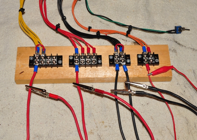
If you want to make the job a little neater, you can use binding post terminals, which will require drilling holes in the power supply. Just make sure they are well insulated as some of the ones at Radio Shack are designed more for plastic project boxes. I chose to use barrier terminals which gives a little more flexibilty with the attachment of clip leads. These can also be obtained at Radio Shack. I spent about $10 on these. Notice how I have grouped the wires together and run a jumper between them. This will allow for the highest current flow without heating any single wire.
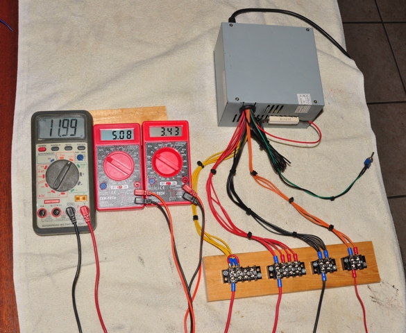
Here you can see each of the voltages provided:
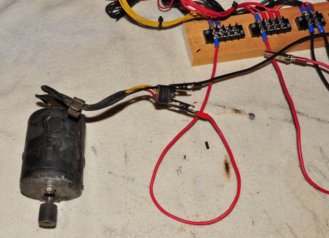
Finally, some tests. Here is a power window motor I found in a box of parts. It tested good.
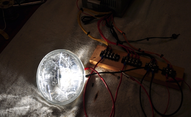
How about a headlight bulb:
If at anytime you short the power supply, fix the circuit and turn the switch off and back on. There is also a switch on the back of the power supply, but it may not reset it.
Here is what you need for a basic setup:
*An ATX type power supply. These are the most common and have been used for at least the past 10 years. You can get them from Newegg.com for about $20:
http://www.newegg.com/Product/Product.a ... 6817170016 or, in my case, I have a computer shop near me that sells used power supplies for $10-$15.
*A 10 ohm 10W ceramic resistor. These can be found in the drawers at Radio Shack for about $2.50 for two. RS also sells them on Ebay for $1.21: http://www.ebay.com/itm/360682691965?ss ... 1439.l2649
*A small single pole single throw (SPST) switch. This is another Radio Shack item that you can get for about $1.50.
*Solder and a soldering iron, a wire cutter and stripper, heat shrink tubing or electrical tape, and two part epoxy, JB Weld, or silicone adhesive.
Here is the power supply I used. It is an old 350W model that can provide 17A at 12V. Another useful aspect is that you can also get 5V for testing instruments or driving electronic circuits if you are interested in that sort of thing, and 3.3V which you can use to test LED's without using a resistor:
Layout the power supply and you will see a lot of wires. The yellow wires are 12V, the red are 5V, the orange are 3.3V and all the blacks are ground. There are some other colors that are not needed.
Cut all of the wires off of the large 20 pin connector. The purple, gray, white, and blue wires are not needed. Pair one of the black wires with the green wire, and another black wire with a red wire.
This is optional, but if you want you can open the power supply and cut off the purple, gray, white, and blue wires at the circuit board. This is safe. just avoid the very large capacitors on the other side of the power supply. They will not have a charge in them anyway if the power supply has not be on in the past day or so.
Glue the 10 ohm resistor to the cooling slots on the side and allow it to harden, then cut the leads off to about 1/4".
Solder a black and a red wire to either side of the resistor and cover the connections with shrink tubing or electrical tape.
Solder the green wire and a black wire to the small switch.
Cut off the remaining connectors and group the colors together. You can stop at this point, but keep in mind that if you are testing a high current part such as a motor, you will want to group several wires together and use a heavier gauge clip lead to attach the 12V and ground wires.
If you want to make the job a little neater, you can use binding post terminals, which will require drilling holes in the power supply. Just make sure they are well insulated as some of the ones at Radio Shack are designed more for plastic project boxes. I chose to use barrier terminals which gives a little more flexibilty with the attachment of clip leads. These can also be obtained at Radio Shack. I spent about $10 on these. Notice how I have grouped the wires together and run a jumper between them. This will allow for the highest current flow without heating any single wire.
Here you can see each of the voltages provided:
Finally, some tests. Here is a power window motor I found in a box of parts. It tested good.
How about a headlight bulb:
If at anytime you short the power supply, fix the circuit and turn the switch off and back on. There is also a switch on the back of the power supply, but it may not reset it.


