Seat belt relay-timer
Posted: Wed Feb 23, 2011 2:05 pm
I cut and pasted a post from tbird (Jim Mills) and hope the images are large enough for anyone that wants to build one of these pieces. Thanks Jim, you've probably saved someone a lot of headaches by showing this work-around. 
This instruction diagram and photo was provide to me in 2002 by Terry Webb from Eastern Canada he is a member of the tbird.org forum I have not tried this but Skip Clark did. Got a PM requesting the info that I sent to Skip so thought I would post it here Maybe Dan should move this to our new tech area.
Sorry for the delay in sending this. I don't have a good program for drawing these things, and when I asked for help, I was told that the circuit was wrong (even thoug it did work). So we've now fixed it, but the drawing leaves a lot to be desired.
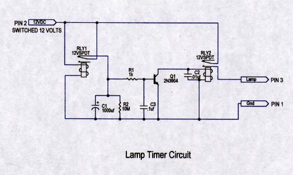
The components are:
RLY1 and RLY2 - SPDT 12v relays
R1 - 1K resistor
R2 -10M resistor
C1 - 1000uf capacitor
C2 - 0.01uf capacitor
C3 - 0.1uf capacitor
Q1 - 2N3904 transistor
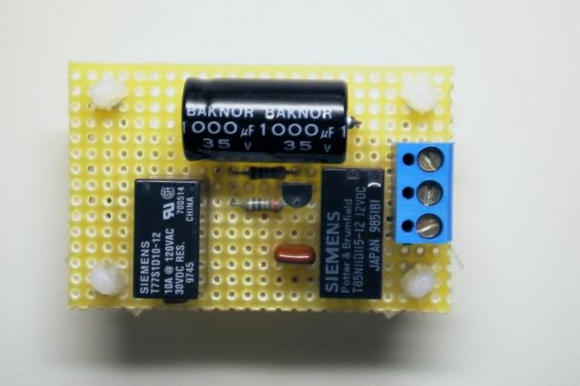
All these are mounted on a little circuit board about 1 1/2 by 2 1/2 inches along with a little terminal block. The wire to the seat belt light was cut and run to pin 2 (switched 12 v in) and then out at pin 3 to the lamp. Pin 1 was connected to ground.
When the car is started, the circuit loads and the values of the capacitors keep the lamp lit for 15 seconds. The lamp then goes out and the relays reset for the next time. Once I had it working, I globbed it up with silicone and mounted it with a tie-wrap against the side of the tunnel underneath the console.
It's not the most elegant solution, but it works, and if someone wanted to spend the time, it could be cleaned up a bit more.
I have attached the scan of the circuit and a photo of the board before I encased it in silicone.
Terry
This instruction diagram and photo was provide to me in 2002 by Terry Webb from Eastern Canada he is a member of the tbird.org forum I have not tried this but Skip Clark did. Got a PM requesting the info that I sent to Skip so thought I would post it here Maybe Dan should move this to our new tech area.
Sorry for the delay in sending this. I don't have a good program for drawing these things, and when I asked for help, I was told that the circuit was wrong (even thoug it did work). So we've now fixed it, but the drawing leaves a lot to be desired.
The components are:
RLY1 and RLY2 - SPDT 12v relays
R1 - 1K resistor
R2 -10M resistor
C1 - 1000uf capacitor
C2 - 0.01uf capacitor
C3 - 0.1uf capacitor
Q1 - 2N3904 transistor
All these are mounted on a little circuit board about 1 1/2 by 2 1/2 inches along with a little terminal block. The wire to the seat belt light was cut and run to pin 2 (switched 12 v in) and then out at pin 3 to the lamp. Pin 1 was connected to ground.
When the car is started, the circuit loads and the values of the capacitors keep the lamp lit for 15 seconds. The lamp then goes out and the relays reset for the next time. Once I had it working, I globbed it up with silicone and mounted it with a tie-wrap against the side of the tunnel underneath the console.
It's not the most elegant solution, but it works, and if someone wanted to spend the time, it could be cleaned up a bit more.
I have attached the scan of the circuit and a photo of the board before I encased it in silicone.
Terry