
This may be an easy repair for others, but this was new territory for me. I didn't really have a grasp of what and where all the parts were until I started digging into it. Once I knew all of the terminology, I was able to order all the correct parts I needed to rebuild it. Although all of this is in Section 8 of the manual, it is nice to have clear color photographs to document the procedure. There are also a lot of torque specifications for all of the suspension fasteners. They can be found in the manual on page 8-32.
Here is a shopping list of what you need to do both sides. Shopping for this stuff was difficult. Prices can vary significantly from different suppliers and some suppliers do not have all of the items to complete the job. So you may find yourself placing two orders or more.
- 2 upper ball joints
2 lower ball joints
2 control arm bushings
2 kits of 2 saddle spring bushings
2 upper control arm (A-arm) shaft kits. Buy the entire shaft with bushings. Some sellers have kits that just include the bushings. If you buy this as a kit, make sure you don't just get the end bushings. As you will see below, the shaft is probably worn out too. I bought all of the parts individually rather than as a kit because I found even the "complete kits" are still missing items that you will need.
2 strut rod bushing kits
2 sway bar bushings
2 stabilizer end link kits. I chose polyurethane links from Amazon. They sent me one red and one blue. So I ordered another one knowing it would match one of the two I already had and sent the odd one back.
2 pair coil spring insulators
2 Tie rod ends as needed if worn
4 Brake backing plate gaskets
- Typical hand tools; sockets, wrenches, pliers
Brake spring tools
Pickle fork
A good vice
1-3/8" socket
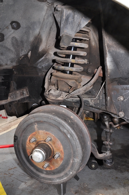
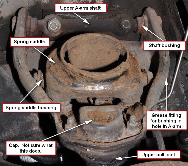
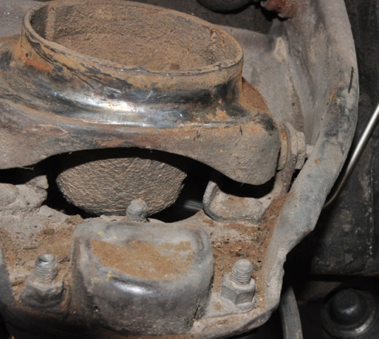
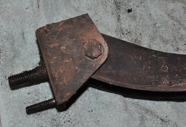
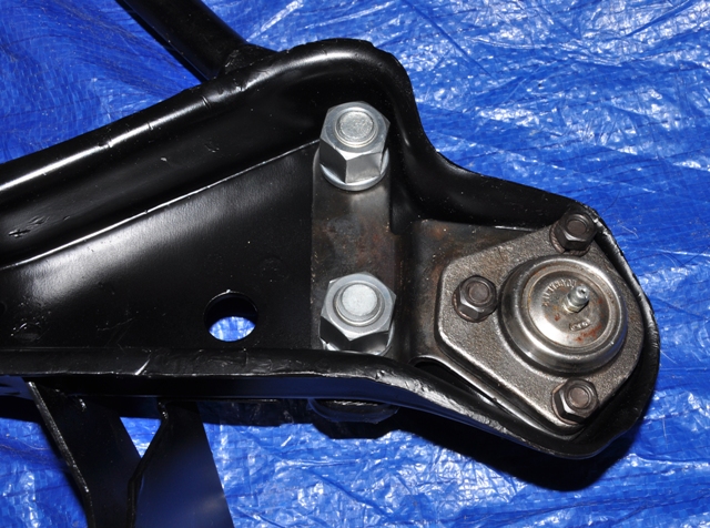
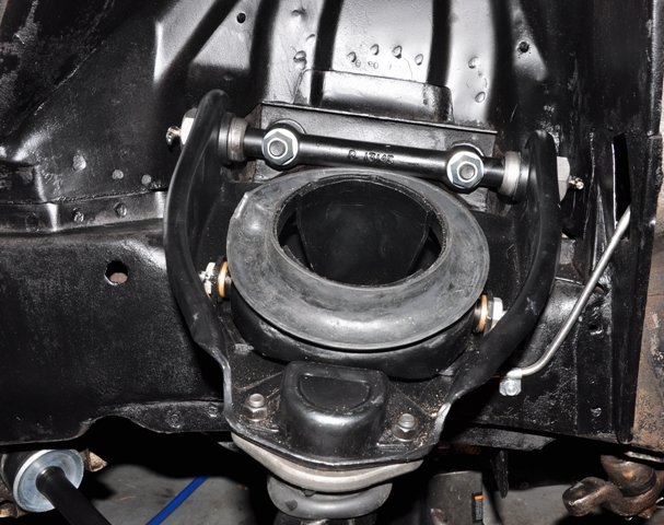
With the spring removed, here are the parts of the upper A-arm.
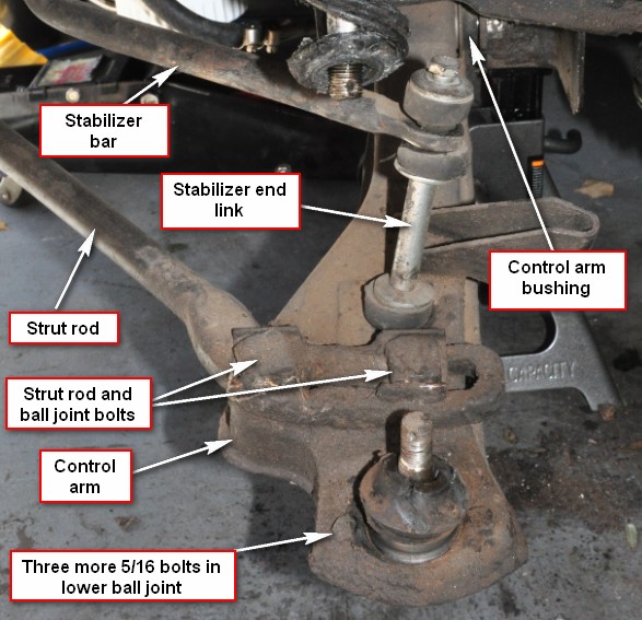
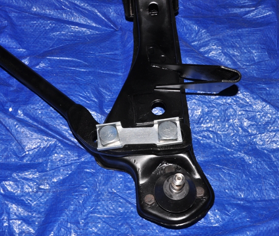
Here are the parts of the lower control arm:
First, remove the fender brace at the cowl and shock tower, top shock absorber nut, and shock tower brace bracket in the engine compartment. Then remove the nut on the bottom of the shock absorber and pull it out from the top.
Next, Remove the upper bumper by removing the four bolts. Unless you have a great memory, I suggest using marked sandwich bags for the fasteners. I cannot remember what happened five minutes ago.
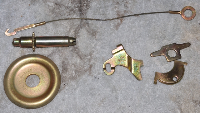
Here I have some incorrect shoes that are lacking holes for two of the retainer springs at the bottom. I have new shoes to correct this problem.
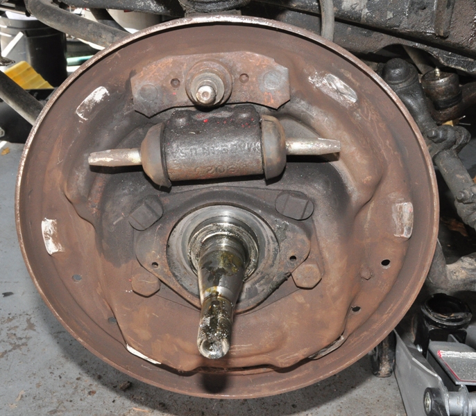
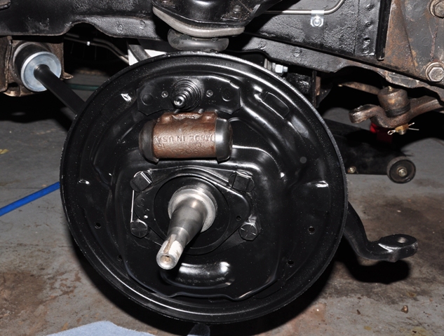
Remove the bearing grease cap and remove the nut and front hub. Strip the brakes down to the cylinder. Take a photo so that you remember where everything goes.
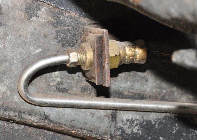
Disconnect the brake line fitting and remove the clip.
Remove the four nuts behind the plate and remove the plate, cylinder, and hose as a unit.
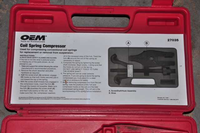
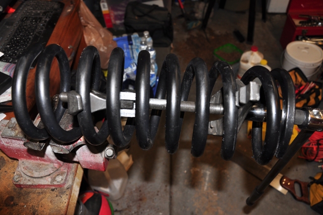
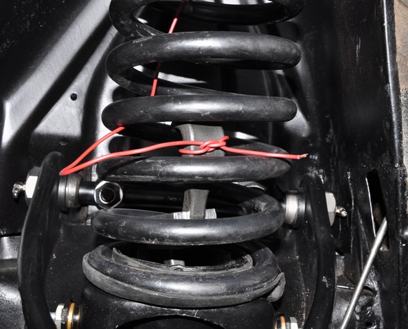
Now remove the spring. I used the OEM 27035 rented from Autozone.
You will see that the bottom piece has two arms. Drop the longer arm first down the hole at the top of the shock tower. Position it as far down on the spring as possible. Insert the upper fork as high on the spring as possible. Lubricate the threaded rod with anti-seize compound and insert it through the hole in the fork and thread it onto the bottom arms.
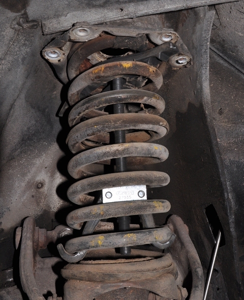
Now comes the hard part. The instructions say not to use an impact wrench on the threaded shaft. So I used a socket and extension and then began tightening the fine thread on the compressor shaft. Eventually, the spring will get loose and start to rotate. I just put a pair of locking pliers on the spring to keep it from rotating.
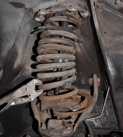
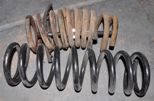
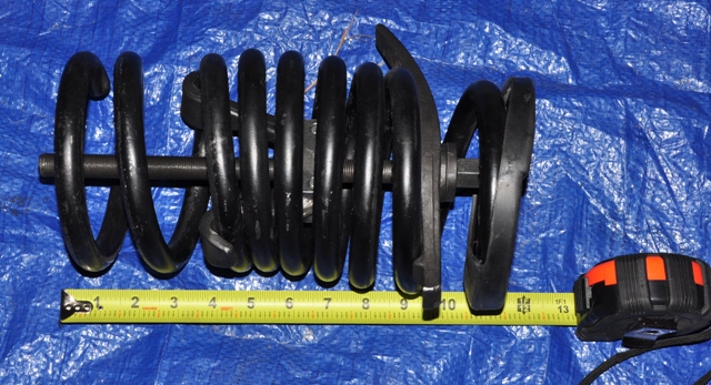
Once the spring is free from the saddle, carefully remove it and set it aside. If you are going to reinstall the same spring, just keep it in a safe place. If you are going to install a new spring, place the spring in a vice and carefully unscrew the compressor. Use caution, but don't be afraid of it. Just keep your body away from the end. Here is the old spring compared to the new one.
At this point, I decided to remove the spring saddle. There are two nuts for each saddle under the A-arm. Remove them and lift the saddle out of the arm.
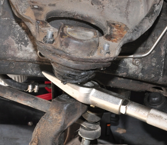
To remove the spindle, remove the nuts on the upper and lower ball joints and the tie rod end. Use a pickle fork to free the spindle from the ball joints and tie rod end.
Remove the two nuts on the shaft and remove the A-arm.
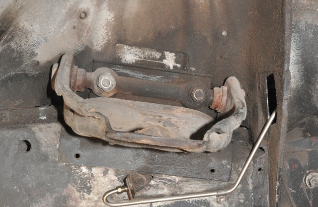
To remove the control arm, remove the nuts under the large square head bolts that connect the strut rod. The ball joint is also secured underneath these bolts in addition to the three bolts around the ball joint itself. Remove the stabilizer end link.
Remove the control arm from the body by removing the large and small nuts inward under the car. This will also remove the camber shims, not shown.
Top view of the lower control arm bushing. This must be pressed out. Use a large socket as a receiver and a smaller socket as a pusher and press it out in a vice. I have a cheap little 6" vice and was able to get it out.
I have media blasted and painted the lower control arm. Now the bushing can be pressed in. I used a 1 1/8" socket as a receiver. Here I am squishing the rubber, no harm was done but you may want to put a thin piece of steel or wood on the vice jaw. Insert the bolt and this component is complete.
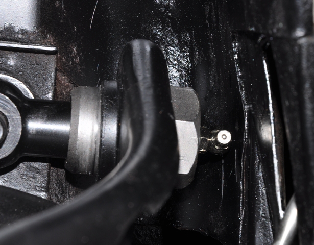
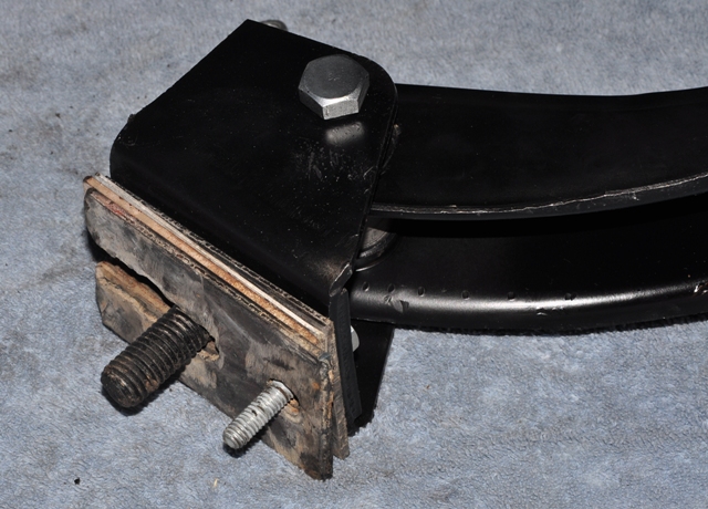
Let's take a look at the saddle spring bushings. These are brass bushings with zerk grease fittings. These must be subject to tremendous stress as they are rather small and must transfer every shock of the wheel to the spring. This nut must be removed first as the bolt is keyed.
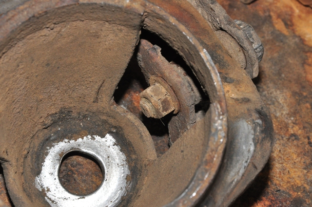
Use a cheap screwdriver or a chisel and force the bolt out.
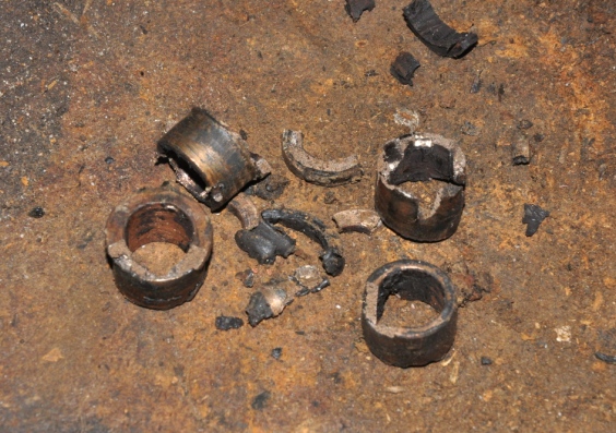
After getting the bolt out, I had to dig the old bushing out. It just fell apart with some gently prying. It's life was long gone.
Here is a view of the cleaned up spring saddle and brackets. Install the new bolt and bushings and insert the grease zerks.
Closer view of spring saddle bracket and bushings. Notice the position of the grease hole.
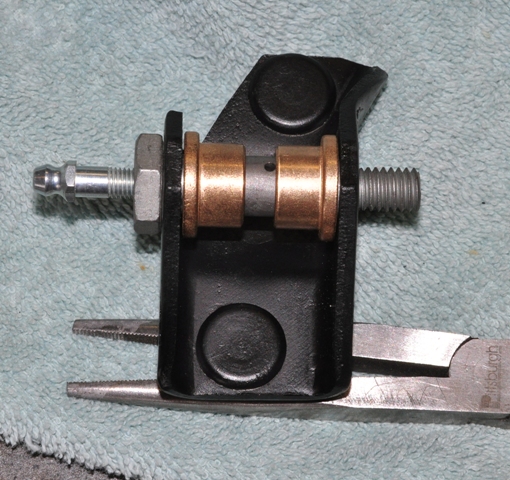
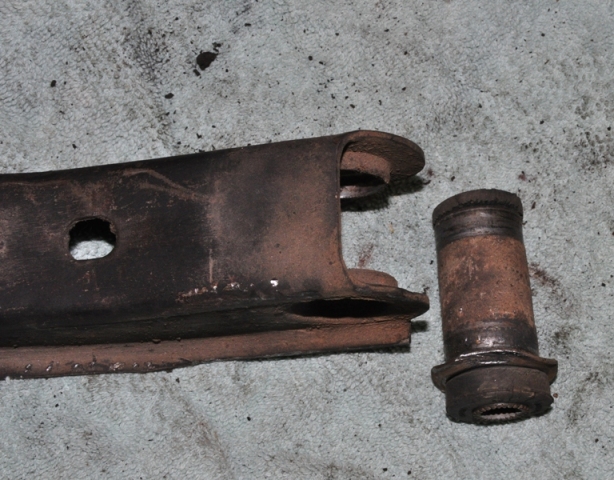
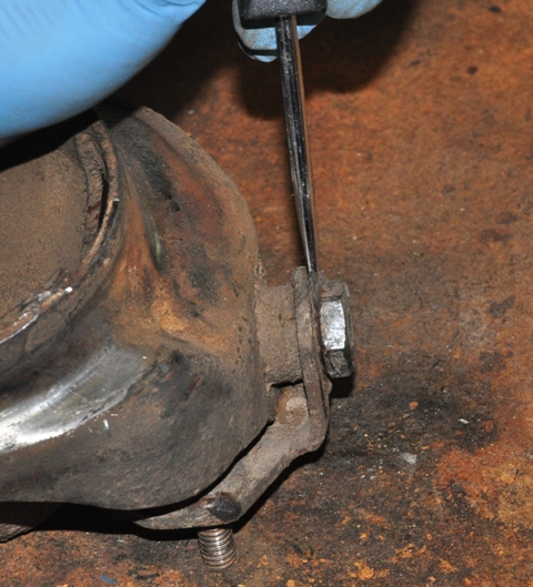
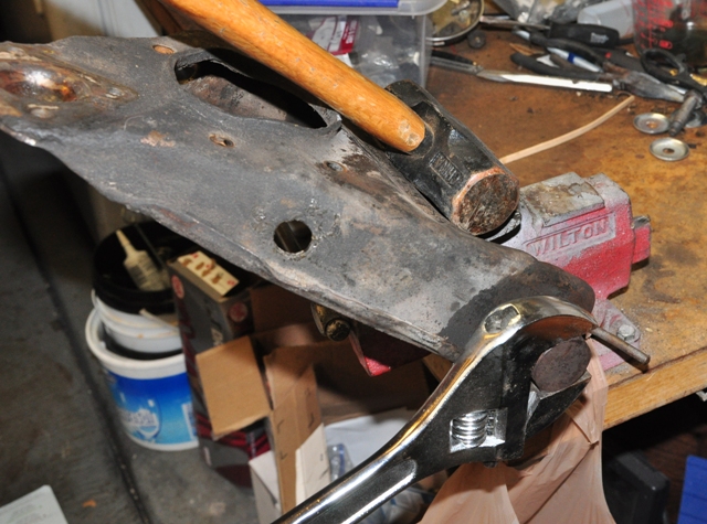
The shaft bushings are threaded into the A-arm and must be unscrewed.
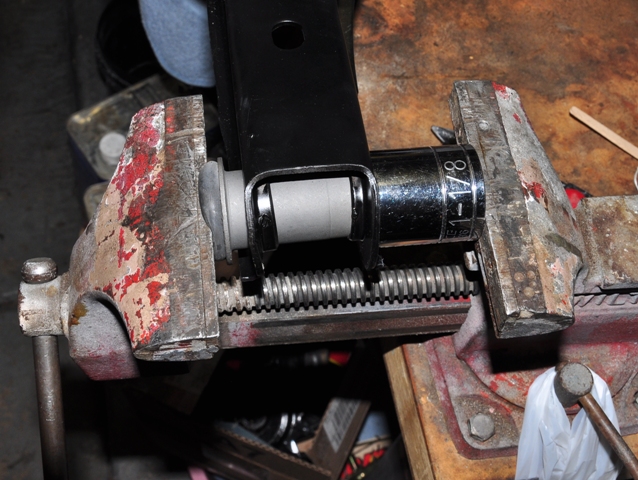
A 12" adjustable wrench was the only tool I had large enough to get around the end bushings. Place the assembly in a vice and break the bushings free.
 '
'Once out, you can assess the damage to the shaft bushing. This is why you want to buy the entire shaft and not just the bushing
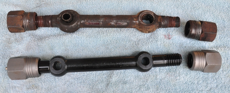
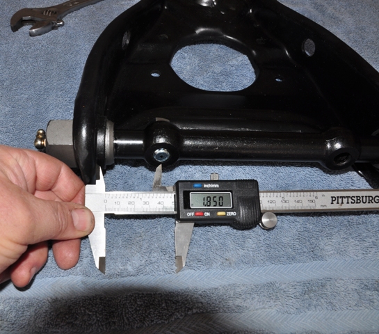
Refer to the shop manual for this procedure. The shaft must be centered within the A-arm. The manual has this dimension as 1.85" from the inside edge of the arm to the center of the bolt hole on each side. Using a digital caliper, I locked that dimension and began screwing the bushings in from each side. The procedure was easier than I thought it would be and once tightened, the holes were exactly at the stated dimension.
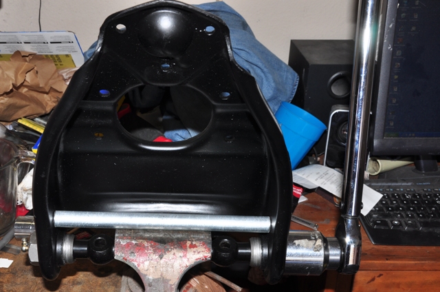
Here I have cut a piece of conduit to slip into the arm to keep it from bending in while setting the final torque of 15 to 25 ft.-lbs. I now have the correct 1-3/8" socket that I found at Autozone.
A word about the zerk fittings. The old shafts did not have zerk fittings, however the new ones do. There is a problem though, The supplier sends straight fittings, making it impossible to get a grease gun onto them. You will have to find standard right angle zerks to replace them.
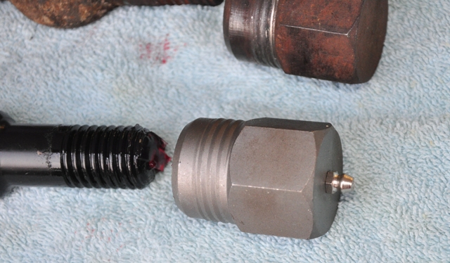
You may also need to place a small washer underneath the zerk to get it to face forward.
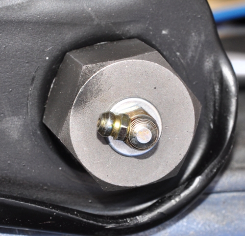
In order to fit the right angle zerks into the body, I had to use the ball end of a ball peen hammer to create some space around it for the grease gun to fit onto it.
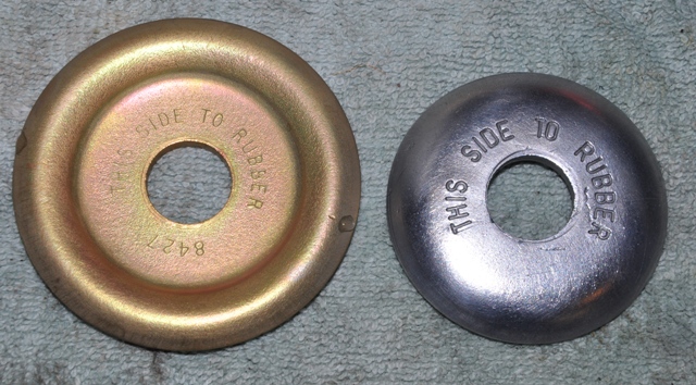
Here are some strut rod details. The new strut rod kit comes with generic washers. The original washers have markings on them that I would like to preserve.
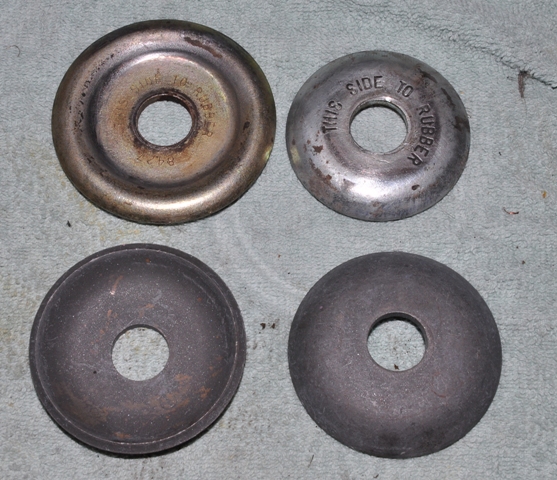
I zinc plated them and chromated the washer that had residual chromate on it.
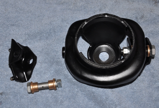
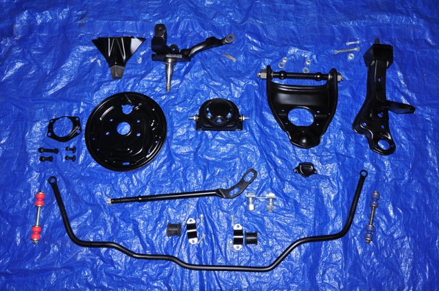
Now all of the subassemblies are finished and ready to be bolted back on. Here is a view of all of the components I have cleaned, repainted, and re-plated.
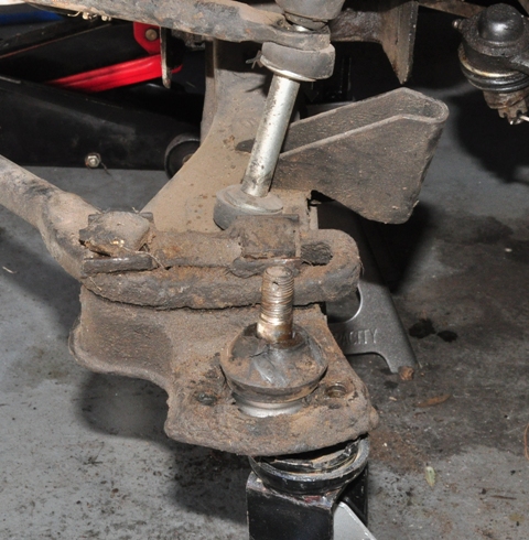
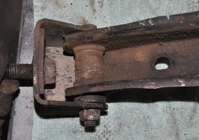
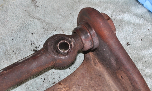
The mounting of the lower ball joint is rather interesting. There are three 5/16" bolts that hold it as well as an extension that bolts it to the two large strut nuts.
The top side of the lower ball joint.
I put the camber shims back on as they were originally. Someone made a homemade shim here. I have purchase a variety of shims from one of the T-Bird suppliers to take to the shop when I get the front end aligned.
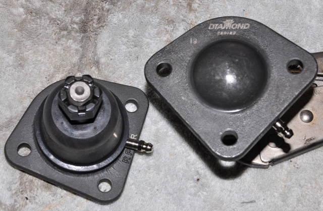
Upper ball joints.
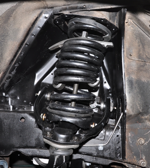
Reassemble everything except the brake backing plate. Install a new spring insulator on the saddle.
Place the spring solidly in the vice and install the spring compressor about where it was when it was removed.
Keep your body away from the end of it and compress it using a breaker bar to about 12" in length.
Carefully take the spring to the saddle and set it place. Use a socket and extension once again to decompress the spring.
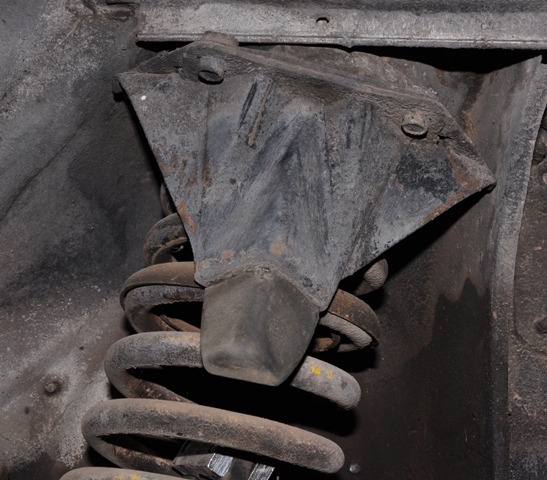
Remove the threaded rod and fork from the top of the compressor. Send a piece of wire down the shock tower hole and attach it to one of the legs of the compressor and pull it out of the top of the shock tower.
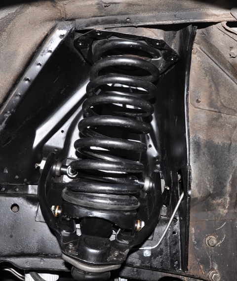
The spring is installed.
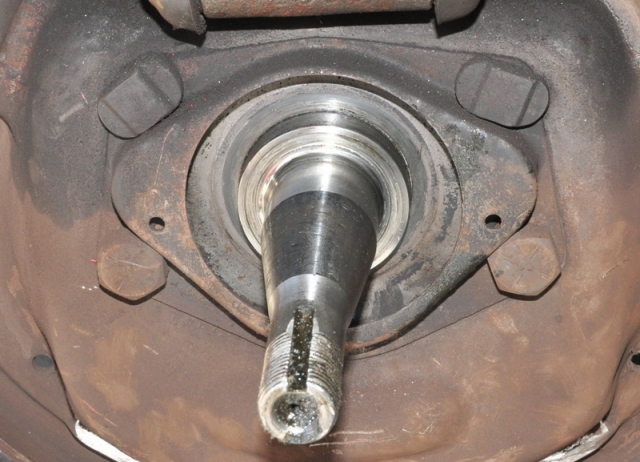
Reassemble the backing plate using new spindle gaskets.
I gave the brake parts a quick zinc plate and chromate dip.
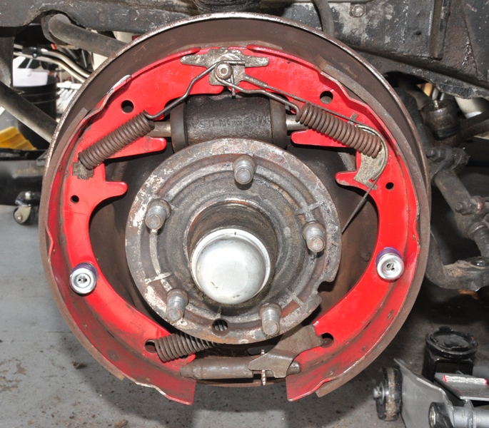
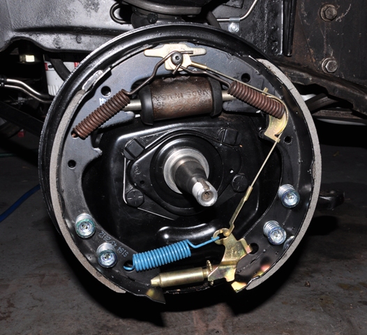
Now the brakes are reassembled using the correct shoes with holes for 4 hold down springs. At this point, just reassemble the hub, install the shock absorber and fender braces, and bleed the brakes, unless you are ambitious and head straight to the other side.
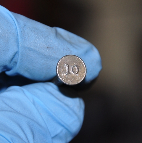
One final note. The T-Bird suppliers can never seem to get the spring kits correct. The pins they send for the front are too short. I called Larry's Thunderbird and got these correct size pins designated with a "10" marking.
Hope this was useful. Good luck. Send me a PM or email me at rt66tbird@comcast.net if you have any questions, comments, or concerns.